OCEAN-CTD Tag User Guide
Please refer to the following guide for details regarding the GEN2 tags.
Contents
1 Applicability
2 Tag Status
2.1 Hibernation Mode
2.2 Mission mode
3 Tag Communication
3.1 Installing the App
3.2 Communicating with a Tag
3.2.1 Serial Bluetooth using Android
3.2.2 Serial Bluetooth using SMRU BLE Dongle
3.2.3 Serial Bluetooth using Windows PC Supporting Bluetooth LE
3.3 Tag Functions
3.3.1 Tag Configuraiton (all tags models)
3.3.2 Self-test
3.3.3 Calibrate the IMU (GSM & continuous sampling tags)
3.3.4 Check and Set the Tag Time/Date
3.3.5 CTD Calibration Interface (CTD/CTF models)
3.3.6 TDR Download (all tags models)
4 CTD Logger Mode
5 Tag Operation
6 Tag Programming
This procedure details how to configure the Gen2 range of tags which use the GSM or interim CTD PCB. Where there is specific applicability to a particular type of tag then this is referred to in the text. Whilst there may be some physical differences (e.g. position of wet/dry sensor discs etc.), the overall functionality in terms of user interface to the tag is largely the same across the whole range (e.g. LED flashing sequences, position of magnetic reed-switches etc).
There are various different modes which the tag can be in, these are:
Hibernation Mode – all tags are shipped in this mode and is the default mode when the tag is not in use/storage as the tag is in a very low power mode.
Mission Mode – this is the mode when the tag is deployed. It exercises all the sensor and data relay protocols of the deployment software. This mode is automatically entered when the tag is activated through the saltwater switch.
Configuration Mode – a temporary mode which the user activates to allows the user to set various tag parameters (such as PTT number, some sample intervals, setting the tag clock etc). It is also the mode which allows the user to download debug and previously stored deployment data.
Hard Reset Mode – this reset all tag parameter to a ‘factory default’ and should not be performed unless advised by SMRU as it has a direct impact on the deployment aspects of the tag. Each of the modes detailed above are characterised by a unique set of LED
sequences displayed by the tag. The location of these LEDs is as shown in the schematic below and the sequence which describes each of them is as follows:2.1 Hibernation Mode
Hibernation Mode is characterised by a single green flash from the green status LED at the rear corner of the tag (approx. once every 10 seconds –It’s not very bright).2.2 Mission mode
In mission mode there are no LEDs flashing. To revert back to hibernation mode then the magnet should be applied to the tag in
the position indicated below. With the magnet in the correct position then a bright red LED on the side of the tag will illuminate. This will be followed a few seconds later by a bright green LED in the rear corner of the tag (i.e. the green LED indicated above).
The magnet should then be removed soon after the green LED illuminates – see photo below for position of magnet.
The green status LED as detailed in Section 2.1 should then once again flash briefly every 10 seconds.
Tag communication using a Gen1 tag was using a TagConfig app on a PC and a Bluetooth Connection. With the Gen2 tags, communication is also using a Bluetooth connection but uses a serial Bluetooth app on an android phone.
Pretty much any serial Bluetooth app will work, but for the purposes of this procedure the example used with use the “Serial Bluetooth” app which is available through the Google Playstore. There is presently no app for apple phones.3.1 Installing the App
Use Google Playstore to install the following app on an android phone: “serial Bluetooth”.3.2 Communicating with a Tag
3.2.1 Serial Bluetooth using Android
With a tag in standby, hold a magnet in the location indicated in the figure below.
A red status LED will illuminate close to where the magnet is positioned. A second red status LED will also illuminate continously at the rear of the tag, see below. Keep the magnet applied for a few seconds until such time as a blue LED starts flashing. This is also at the rear of the tag.
Remove the magnet when the blue LED starts flashing once every 4 seconds. With the magnet removed the red LED at the side of the tag will stop illuminating, whereas the red led at the rear of the tag will continue to illuminate until a connection
is established.Run the Serial Bluetooth App on the phone.
Use the Menu Item (= symbol) to select devices.
Select “Bluetooth LE” and then press “Scan” to search for new devices.
The tag will look something like “RN–”. Once identified, press on the device name RN– to connect to the tag.
Once connected you should see something like the following: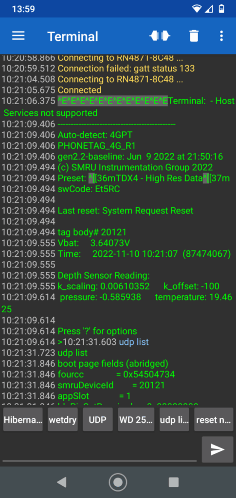
When a connection is established then then the red LED at the rear of the tag stops illuminating, there will be brief illumination from an orange adjacent LED, and the blue LED will then start double flashing every second or so.
If the tag does not connect then repeat the above, assuming the blue Bluetooth LED is still flashing on the tag. If the blue Bluetooth LED is no longer flashing then the magnet will need to be re-applied (the blue Bluetooth LED times-out after a minute or so and the tag reverts back to hibernate again). In the example above it took 2x connection attempts.
To exit this mode, type “hibernate” in the textbox and then press the arrow key.NOTE: Commands are case-sensitive
The response will be “Connection Lost” and the blue Bluetooth LED on the tag will stop flashing and the green status LED will recommence flashing once every 10 seconds.3.2.2 Serial Bluetooth using SMRU BLE Dongle
The dongle has a multicolour LED and a blue LED. The blue LED indicates BLE connection status in the same manner as the tag. The multicolour LED is used to indicate dongle operating state, according to the following table:solid yellow terminal: waiting for PuTTY connection off terminal: waiting for commands (via
PuTTY)blinking green polling: first 10 second idle period flashing red polling: second 10 second idle solid red polling: 20 second scanning for RN4871-
????solid green connected to RN4871-???? It is recommended that PuTTY is used as the terminal emulator running on the PC. The dongle operation has been verified with PuTTY and the following instructions are tailored towards a PuTTY setup.
3.2.2.1 Setting up PuTTY with the dongle
When the dongle is plugged in to the PC, the multicolour LED will be solid yellow, indicating that the dongle is waiting for PuTTY to be launched.When the dongle is first plugged into a PC, we need to determine what COM port the dongle appears on that PC. Use Device Manager to determine the ‘COM’ port of the dongle for serial communications. The dongle will enumerate as a ‘JLink CDC
UART’. In the case below, it appears on COM port COM27. Normally this port will be assigned to the dongle on this PC and we will only need to do this check once.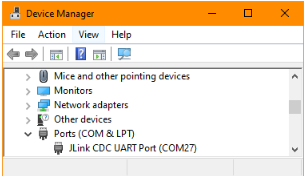
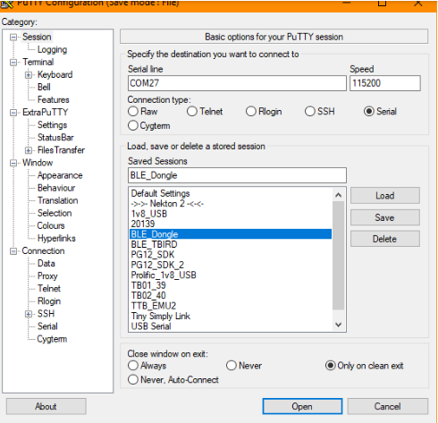
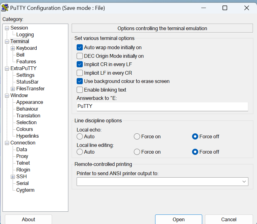
The next step is to setup PuTTY to talk to the dongle on the assigned COM port. In PuTTY, the ‘Session’ settings should be Serial at 115200 baud, on the ‘Serial line’ we identified above (COM27 in this case).
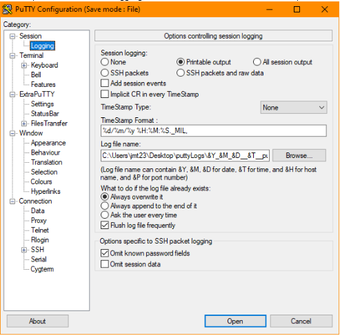
Also, if you use the PuTTY logging feature, it is recommended that only ‘Printable output’ is logged.
The dongle does echo any input from the PC and has a built in line editor, so in ‘Terminal’ settings, it is recommended to Force off ‘Local echo’ and ‘Local line editing’. The dongle uses the ‘new-line’ character (aka ‘line-feed’) at the end of each line and it is found that checking ‘Implicit CR …’ and ‘Implicit LF …’ gives the best mapping.
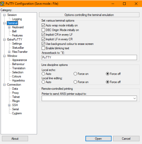
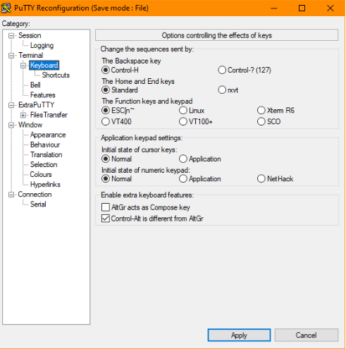
To allow the dongle to detect backspace and arrow keys correctly, make sure that the Keyboard settings are as shown below.
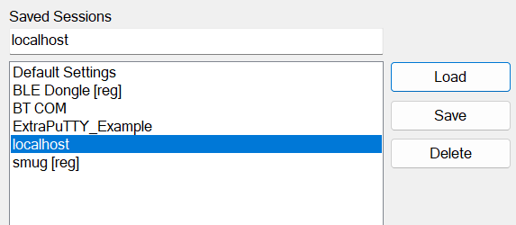
Once all these settings have been set, go back to the ‘Session’ tab, type a name such as BLE Dongle in the ‘Saved Session’ field, and hit Save. Saved sessions can be opened by loading the session and pressing the Open button, or simply double clicking the saved session name in the session list. When you open the session, the terminal should display something like this, and the yellow LED will go off.

3.2.2.2 Connecting to a tag over BLE using ‘poll’
When only one tag is being used within the range of the dongle, the simplest method of connecting to a tag is to have the dongle automatically search for and then connect to the tag.
With a tag in standby, hold a magnet in the location indicated by the red box in the figure below.
A red status LED will illuminate close to where the magnet is positioned.
A second red status LED will also illuminate continuously at the rear of the tag.
Keep the magnet applied for a few seconds until such time as a blue LED starts flashing.Remove the magnet when the blue LED starts flashing once every 4 seconds. With the magnet removed the red LED at the side of the tag will stop illuminating, whereas the red led at the rear of the tag will continue to illuminate until a connection
is established.Position the tag on top of the Bluetooth dongle. Ideally the two should be strapped together if the pair are to be immersed in seawater.
Open the Putty connection.
Type poll at the ‘>’ prompt. The terminal should display the following.
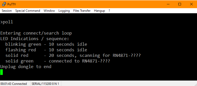
The dongle scans for a tag for 20 seconds (solid red LED). If a tag was not found it will idle for 20 seconds (blinking green for 10 seconds, then blinking red for 10 seconds) then scan again for 20 seconds. It will repeat this process until a tag is found and connected to (solid green LED).
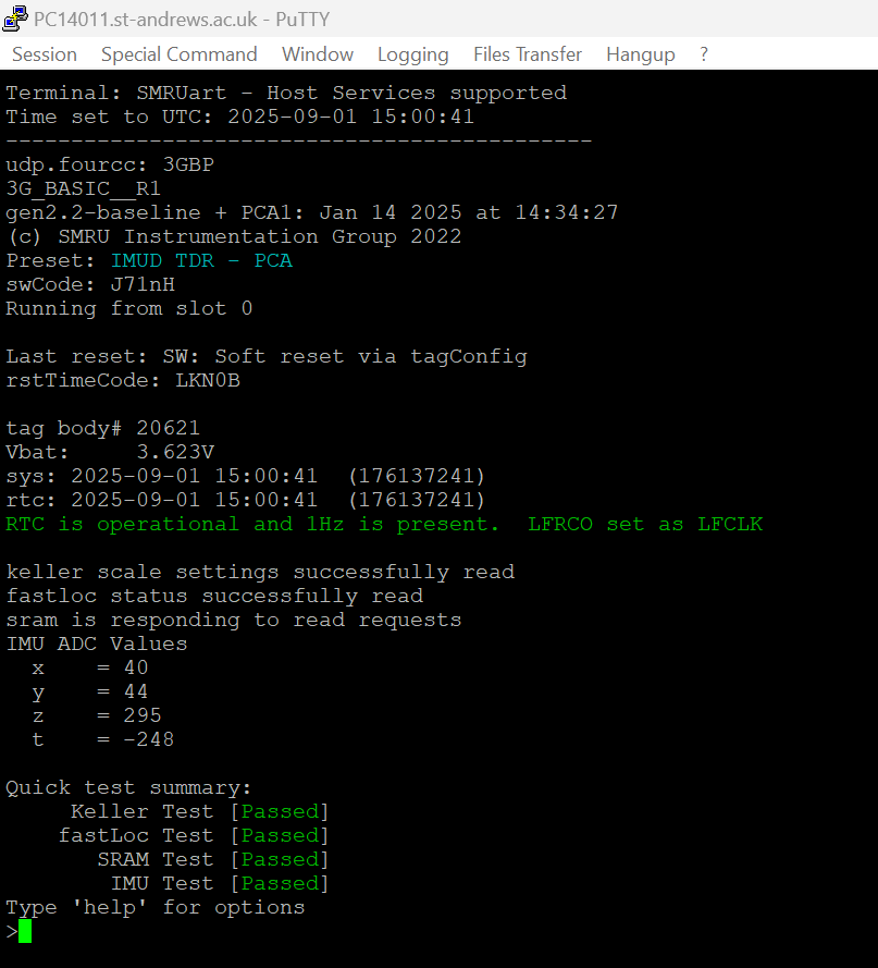
When the dongle is connected to the tag it will relay tag serial data (tagConfig) to PuTTY and vice versa. A successful connection will display tagConfig and should look something like this:

To exit the tag connection, type “hibernate” then carriage return after the command prompt.
3.2.3 Serial Bluetooth using Windows PC Supporting Bluetooth LE
The following procedure is for Windows PCs which support Bluetooth LE (Low Energy Bluetooth). Most new PCs which are installed with Bluetooth 5.0 will support Bluetooth LE.If the PC does not support Bluetooth LE then it may be possible to use an external Bluetooth Dongle connected to the PC (e.g Edimax Bluetooth 5.0, BT-8500). The remainder of this procedure assumes the PC supports Bluetooth LE.
3.2.3.1 Configuring the PC with SMRUart and PuTTY
- Download SMRUart from the downloads page and uncompress into the root directory (c:) for the PC. The folder should be called SMRUart.
- Create an additional folder with the SMRUart folder called “Log Files”.
- Run the dotnet-runtime application.
- Navigate within the folder and run the Putty.exe application. This should be in the following directory: C://SMRUart/extraPutty/Bin
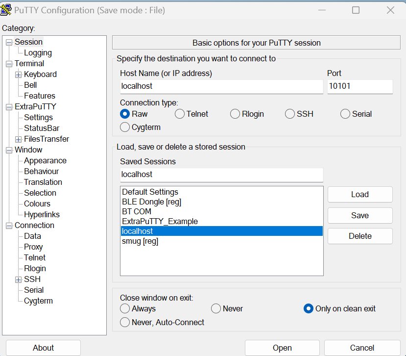
- The window below (or very similar) should open.
- Create a new session. Entering the Host Name as “localhost” and the port as “10101”. Type localhost in the Saved Sessions and press save.
- Make additional changes on the following pages as per the below images:
- Session Logging
- Terminal
- Navigate back to the Session Page, highlight “localhost” and press the “Save” button.
- Now close the Putty App, or press “Cancel”. Do not press connect.

3.2.3.2 Establishing a serial connection with SMRUart
- Navigate to the SMRUart folder on the c:\ drive
- Place the tag into Bluetooth mode:
With a tag in standby, hold a magnet in the location indicated in the figure below.

A red status LED will illuminate close to where the magnet is positioned. A second red status LED will also illuminate continously at the rear of the tag see below. Keep the magnet applied for a few seconds until such time as a blue LED starts flashing. This is also at the rear of the tag (see below) Remove the magnet when the blue LED starts flashing once every 4 seconds.With the magnet removed the red LED at the side of the tag will stop illuminating, whereas the red led at the rear of the tag will continue to illuminate until a connection is established.
- Establish the Bluetooth address for the tag as follows:
- Navigate to “Bluetooth & Devices > Devices > Add a device”
- The Bluetooth address runs with the prefix RN… So, for the tag in the example above, the tags address is RN4871-2F89.
- You may need to select ‘Advanced’ under the Bluetooth devices discovery option in order for the tag to appear in the Add a device window.
- Do not try to connect to the tag – press “Cancel”
- Within the SMRUart folder, run the command line app, CMD.EXE
- This opens up a command line window.
- In the command line prompt, type the following and press the return key.
- For Bluetooth addresses RN4871:
- Type Connect xxxx
- For Bluetooth addresses RN4870:
- Type Connect0 xxxx
- Where xxx are last 4 digits for the Bluetooth address.
- For the example above, type “Connect 2F89” and press return.
- If this doesn’t work the syntax may need to be typed as follows: “.\Connect 2F89”
- For Bluetooth addresses RN4871:
- A new script window will open, followed shortly afterwards by a connection window, the latter looking something like the following:
If you see the above, then congratulations !!!
- To close the app, type “hibernate” or “deploy emp” followed by return (which you chose to use depends upon whether you wish to preserve the data in the FLASH or not) – see Section 3.3.
- Close any remaining windows (serial port and connection windows) in the usual way.
3.3 Tag Functions
Note: Commands are case-sensitive
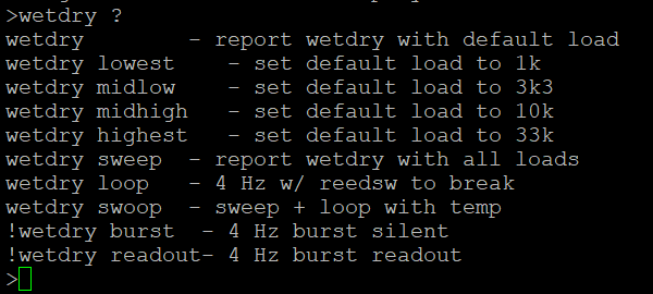
Note: The following is not a comprehensive document. Depending upon the tag type or version of tag software installed, the following may or may not be supported. To view a list of available functions, type “help”. The following is an example of the list of functions supported. Additional help for each of the functions available is possible by typing: “function ?” . For example:
3.3.1Tag Configuration (all tags models)
The Tag configuration may be viewed by typing “kvp list”. To exit, type “hibernate”.
This is where user configurable parameters exist, such as:
- Wet/dry threshold
- PTT Numbers
- Thermistor calibration values (where appropriate)
- IMU calibration data
- Various sampling and transmission parameters
What is presented is dependent upon the version of code on the tag.
3.3.2 Self-test
The tag can be made to run-through an internal self-test. All should pass apart from perhaps the thermistor test. To run the test type “selftest”. The following is a typical screenshot:
(NOTE: Commands are case-sensitive)
To exit, type “hibernate” and then the key.3.3.3 Calibrate the IMU (GSM & continuous sampling tags)
For tags which use the IMU (accelerometer), the IMU should be calibrated in all 6-axes. This is achieved by using the Serial terminal app to set the tag running in a calibration mode and, positioning the tag to rest on one of its 6-axes in turn. The sequence would be as follows:- Establish communication with the tag.
- Type “imu cal”
- Rest the tag on the bench in the first axis (axis 1) and wait for the tag to indicate with a very bright green flash near where the magnet was applied. It is important that the tag is not moved at all whilst the green LED is illuminated.
- Move the tag to the second axis (axis 2) and once again wait for the tag to indicate with a very bright green flash.
- Repeat the sequence (c-d) until all 6-axes are completed.
- The order in which the 6-axes are done does not matter. Each should be roughly perpendicular to each other.
- There are 10 seconds to move the tag to the next position in Item (d).
- The following is a typical partial screenshot once complete:

- The full set of results can be seen by typing “udp list”.
- The values would typically be in the following sort of range:
- imuXScale = 0.00435086
- imuYScale = 0.00459159
- imuZScale = 0.00448255
- imuZDepthCorrection = 0
- imuXOffset = 11
- imuYOffset = 43.125
- imuZOffset = 7.125
- imuRange = 2
- To exit, type “hibernate”.
3.3.4 Check and Set the Tag Time/Date
3.3.4.1 Check Tag Time/Date (all tags models)
To check the tag time and date, once connected using Bluetooth, type: “time”.The time is a 24hr clock and must be in UTC and needs to be accurate to within a few seconds. See below on how to set the date and time.
3.3.4.2 Set Tag Time/Date (all tag models)
To set the tag time and date, first establish a Bluetooth connection using the Serial Bluetooth App. Once connected, use the time function with the following syntax:- The date and time can be set separately, changing one does not change the other.
- For the date, type:
- “time yyyy-mm-dd”.
- For the time, type:
- “time hh:mm:ss”.
- Alternatively, both may be changed at the same time by typing:
- “time yyyy/mm/dd hh:mm:ss”.
- Remember to check the date and time are set correctly afterwards by typing “time”.
3.3.5 CTD Calibration Interface (CTD/CTF models)
When connecting to the tag in tagConfig mode, the initial output should look very similar to this: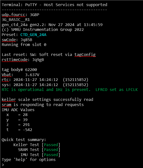
Typing help at the command prompt will display available commands:

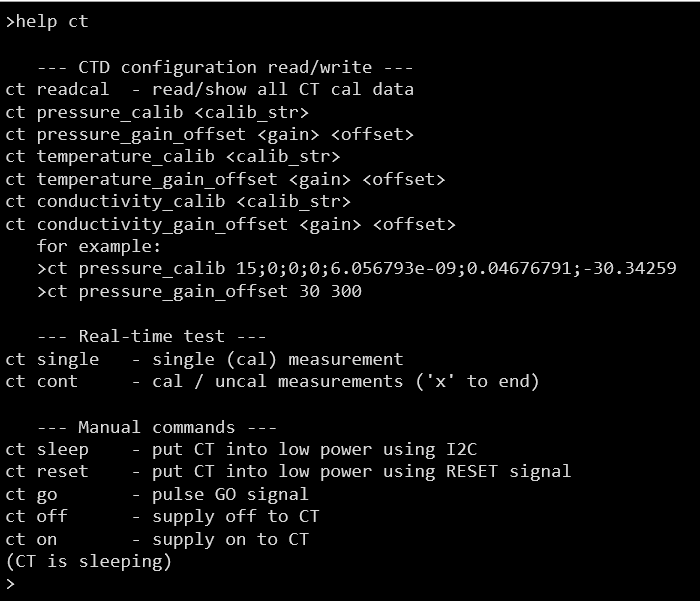
The ct command is used to calibrate the Valeport CT Head. Typing help ct will show the options and parameters for this command:
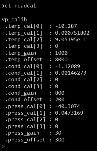
The first thing you may want to do is read the current calibration values with ct readcal.
Then use the ct cont command to take continuous readings once per second, alternating between calibrated and uncalibrated measurements:

Note: the measurements will continue until the ‘x’ key is pressed.
Once the measurements have been analysed to generate the calibration and gain/offset values, use the xxx_calib and xxx_gain_offset command options, where xxx is conductivity or temperature.
Note that the calibration strings are the same format as was used for the first generation tags.
Once the new calibration values are written, use ct readcal again to double check that they match the expected values: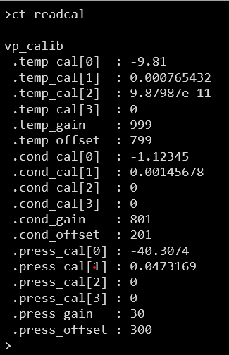
After calibration, return the tag to Hibernation mode. For Fluorometry tags, a magnet needs to be reapplied to the tag to put the tag back in Hibernation mode, see section 2.2.
Depending on the terminal program used to connect to the tag, it may be possible to cut and paste calibration commands (one at a time) directly from excel. For example, the examples above used PuTTY as the terminal, and a generated command in an excel cell could be copied directly to PuTTY by using on the cell in excel, and then right clicking on the PuTTY terminal window to paste the cell contents.
3.3.6 TDR Download (all tags models)
This function is used to download data from FLASH memory, whether this be from a deployed tag, or one which has been on test (such as at-sea tests or in a laboratory environment).
Data in FLASH is stored in ‘Pages”, with each page comprising a block of data. The following commands are used to access the FLSH data.
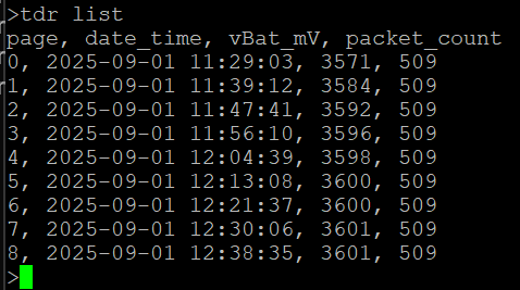
- “tdr list” – this lists all the available data pages which may be downloaded from the tag
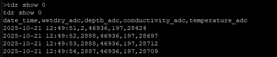
- “tdr show” – this is used to download data pages, for example “tdr show 2 5” would download data pages 2 to 5 (inclusive). In this manner it is not necessary to download all the pages in one single download attempt.
For SMRUart the data is stored on the C:\ drive in the directory specified putty configuration and is prefixed with the date.
For Android this is printed to screen, though there is an option to log to file in the terminal window under the “Data” tab.
In the following example there are 8 pages of data with the starting timestamp for each of the pages indicated:
To download all 8 pages, first type “ct readcal” (to get the calibration values for the tag), then type “tdr show 0 8”. As mentioned above, downloads can be specified from any page to any page so if there is a problem during a download then the whole sequence does not need to be started all over again.
Logger is a sub-context of the CTD TagConfig program that allows CTD readings to be logged to flash memory in real time at a user-specified interval.
After connecting to the CTD tag by BlueTooth, using SMRUart on a PC or by Android app, simply run the logger command, by typing ‘logger’.This will return a command line prompt that reminds you that you are in the logger context.
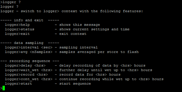
For a list of the available instructions, simply type “help” :
logger>help
help
—– info and exit —–
logger>help – shows this message
logger>status – shows current settings and time
logger>exit – exit context
—– data sampling —–
logger>interval <sec> – sampling interval
logger>avg <nSamples> – samples averaged per store to flash
— recording sequence —
logger>delay <hrs> – delay recording of data by <hrs> hours
logger>wait_wet <hrs> – further delay until wet up to <hrs> hours
logger>record <hrs> – record data for <hrs> hours
logger>cont_wet <hrs> – continue recording while wet up to <hrs> hours
logger>start – start sequence
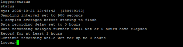
To see the current configuration, type “status”:
logger>status
“status
sys: 2025-10-21 12:45:42 (180449142)
Sampling interval set to 900 seconds
1 samples averaged before storing to flash
Data recording delay set to 0 hours
Data recording delayed further until wet or 0 hours have elapsed
Record for at least 1 hours
Continue recording while wet for up to 0 hours”
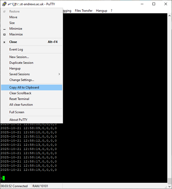
Copy the session data to the system clipboard by clicking on the computer icon in the top left of the Putty window. It can then be pasted into a text editor and saved as a CSV file for importing into a spreadsheet. On Android, you can use the app’s logging option to record the entire session and then transfer the log file by email.

All tags are shipped in hibernation mode. In this state the tags can be left for many months with only minimal power drain from the battery. The tag is in hibernation mode when the green status LED flashes once every 10 seconds (refer to Section 2.1).
5.1 Tag Activation and Functionality
The tag enters mission mode automatically when it detects immersion in sea-water.
Upon immersion in sea-water, the green status LED stops the 10 second flashing. Unlike the GEN1 tags, there is no other indication of mission mode. The process of activation is quite quick. Immersion (or shorting the contacts with a piece of wire) only takes a few seconds.Upon removal from sea-water, the tag will periodically perform Argos transmissions. Please note however, the tag automatically enters a transmission schedule. This means that after a few hours the tag will cease transmissions once the transmission quota is reached and will only re-commence transmission when the next quota is released by the tag software. This quota release works on a 7-hour cycle. The purpose of this is to preserve battery life. Refer to Section 2.2 on how to revert the tag back to hibernation mode.
5.1.1 Tag Testing
Please perform the following tag test prior to deployment:
Check that the tag is in hibernation mode: i.e. the green status LED is flashing once every 10 seconds.
Activate the tag by shorting the two wet / dry contacts using a piece of wire. Almost any wire is suitable for this. Hold in position for 5 seconds.Remove the shorting wire and check the green status LED is no longer flashing. Position the tag in a position with good visibility of the sky and leave for several hours (minimum of 6 hours). If more than one tag is being tested at any one time then the tags should ideally be spaced several feet apart. Put the tag back in to sleep mode after >6 hours using a magnet – refer to Section 2.3.
The tag’s location and ARGOS / GSM diagnostic data will update automatically on the SMRU web-site http://www.smru.st-and.ac.uk/protected/technical.htmlArgosweb may also be used to check for uplinks.
It is not presently possible to program the tags over Bluetooth – the tags must be returned to SMRU.