TIDE-GSM Tag User Manual
Contents
1 Applicability
2 Tag Status
2.1 Hibernation Mode
2.2 Mission mode
3 Tag Communication
3.1 Installing the App
3.2 Communicating with a Tag
4 Tag Operation
4.1 Tag Activation – Mission Mode
4.1.1 Tag Testing – GSM Tags
5 Appendix
5.1 Tag Functions
5.1.1 Configuration
5.1.2 Self-test
5.1.3 Calibrate the IMU
5.1.4 Check and Set the Tag Time/Date
5.1.5 Deployment Preparation
5.1.6 TDR Data
5.2 Reversion to Standby
5.2.1 Bluetooth Mode
5.2.2 Mission Mode
5.3 Use in Fresh-water
5.3.1 Lake Saimaa
5.3.2 Wet/Dry Load and Threshold Setting
5.3.3 Tag Check
This procedure details how to establish communication with the TIDE-GSM tags (previously named 3G-Basic GSM tags) and run various functions.
Applicable for software builds from Jan 2025 (PCA code, J71nH)All tags are shipped ready to be deployed and no prior adjustments are required.
There are various different modes which the tag can be in, these are:
Hibernation Mode – all tags are shipped in this mode and is the default mode when the tag is not in use/storage as the tag is in a very low power mode.
Mission Mode – this is the mode when the tag is deployed. It exercises all the sensor and data relay protocols of the deployment software. This mode is automatically entered when the tag is activated through the saltwater switch.
Configuration Mode – a temporary mode which the user activates to allows the user to set various tag parameters (such as PTT number, some sample intervals, setting the tag clock etc). It is also the mode which allows the user to download debug and previously stored deployment data.
Hard Reset Mode – this reset all tag parameter to a ‘factory default’ and should not be performed unless advised by SMRU as it has a direct impact on the deployment aspects of the tag.
Each of the modes detailed above are characterised by a unique set of LED sequences displayed by the tag. The location of these LEDs is as shown in the schematic below and the sequence which describes each of them is as follows:
2.1 Hibernation Mode
Hibernation Mode is Characterised by a single green flash from the green status LED at the rear corner of the tag (approx. once every 10 seconds –It’s not very bright).
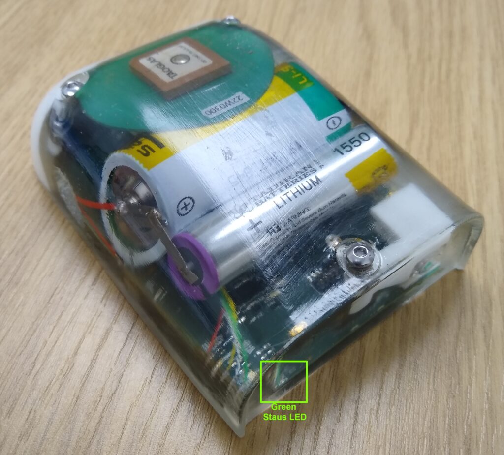
2.2 Mission mode
In mission mode there are no LEDs flashing.
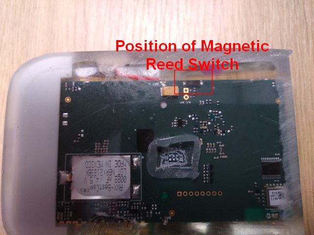
To revert back to hibernation mode then the magnet should be applied to the tag in the position indicated below. With the magnet in the correct position then a bright red LED on the side of the tag will illuminate. This will be followed a few seconds later by a bright green LED in the rear corner of the tag (i.e. the green LED indicated above).
The magnet should then be removed soon after the green LED illuminates.
The green status LED as detailed in Section 2.1 should then once again flash briefly every 10 seconds.
Tag communication using a Gen1 tag was using a TagConfig app on a PC and a Bluetooth Connection. With the Gen2 tags, communication is also using a Bluetooth connection but uses a serial Bluetooth app on an android phone.
Pretty much any serial Bluetooth app will work, but for the purposes of this procedure the example used with use the “Serial Bluetooth Terminal” app which is available through the Google Playstore.3.1 Installing the App
Use Google Playstore to install the “serial Bluetooth Terminal” app on an android phone.3.2 Communicating with a Tag
With a tag in standby, hold a magnet in the location indicated by the red box in the figure below.

A red status LED will illuminate close to where the magnet is positioned.
A second red status LED will also illuminate continuously at the rear of the tag, see below.
Keep the magnet applied for a few seconds until such time as a blue LED starts flashing. This is also at the rear of the tag (see below).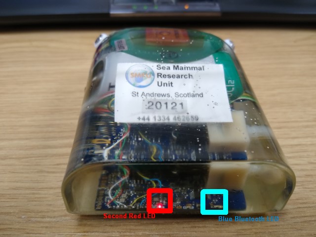
Remove the magnet when the blue LED starts flashing once every 4 seconds. With the magnet removed the red LED at the side of the tag will stop illuminating, whereas the red led at the rear of the tag will continue to illuminate until a connection is established.
Run the Serial Bluetooth App on the phone.Use the Menu Item (= symbol) to select devices.
Select “Bluetooth LE” and then press “Scan” to search for new devices.
The tag will look something like “RN****-****”. Once identified, press on the device name RN****-**** to connect to the tag.
Once connected you should see something like the following:
When a connection is established then the red LED at the rear of the tag stops illuminating, there will be brief illumination from an orange adjacent LED, and the blue LED will then start double flashing every second or so.
If the tag does not connect then repeat the above, assuming the blue Bluetooth LED is still flashing on the tag. If the blue Bluetooth LED is no longer flashing then the magnet will need to be re-applied (the blue BluetoothLED times-out after a minute or so and the tag reverts back to hibernate again). In the example above it took 2x connection attempts.
To exit this mode, type “hibernate” in the textbox and then press the arrow key. NOTE: Commands are case-sensitive.
The response will be “Connection Lost” and the blue BluetoothLED on the tag will stop flashing and the green status LED will recommence flashing once every 10 seconds.
4.1 Tag Activation – Mission Mode
This version of tag differs from previous ones in that they have 3x wet/dry contacts. The front two tags are connected together.
To activate a tag it is necessary to short between the contact at the rear of the tag and one of the contacts at the front of the tag.
The short can be using either a piece of wire or by dunking in sea-water. In either case the short should be for around 10 seconds to ensure activation.
Tag activation will be characterised by the green status LED in the rear corner of the tag ceasing to flash once every 10 seconds (see Section 2.1).
With an active tag, you may occasionally see a brief orange flash from underneath the GPS patch antenna on the top of the tag and/or a bright red LED from the front corner. These are normal during tag operation. The orange LED indicates a GPS grab, the bright red LED, a text or data call.4.1.1 Tag Testing – GSM Tags
All tags should be checked shortly prior to deployment. This checks the clock is set correctly and the data relay connection back to SMRU – this is particularly important for GSM tags – to check data connectivity with a new provider. GSM tag testing should be performed somewhere with known good coverage.
To check the tag, activate by shorting the wet/dry contacts as described in Section 4.1. Then, leave the tag outside for at least overnight – somewhere within known GSM coverage (h check the data relay) and very good visibility of the sky (to check the GPS function).
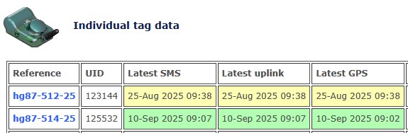
Inspect the data the next morning on the data portal provided by SMRU.The things to look out for are as follows:
Front page of your data-page: Latest SMS, uplink and GPS data which should highlight in green.
Scroll to the bottom of the main page and look for the following links:
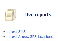
Press on “Latest Argos/GPS locations.” link
You should see recent accurate GPS locations for each of the tags from the previous night’s testing. The data should be in green (unlike the example below):

Since the tags are in haul-out, the GPS location frequency is hourly. There should be locations in the Lat and Long columns.
The tags may now be placed back in to hibernation using a magnet – refer to Section 2.2 which explains this process.
It is only necessary to follow these steps if instructed by a member of the SMRU Instrumentation Team. All tags are shipped calibrated and ready to be deployed.
5.1 Tag Functions
5.1.1 Configuration
The Tag configuration may be viewed by typing “UDP list”. (NOTE: Commands are case-sensitive)
To exit, type “hibernate”.
5.1.2 Self-test
The tag can be made to run-through an internal self-test. All should pass apart from perhaps the thermistor test. To run the test type “selftest” and then the key. The following is a typical screenshot:
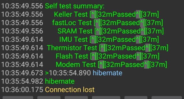
To exit, type “hibernate”.
5.1.3 Calibrate the IMU
For tags which use the IMU (accelerometer), the IMU should be calibrated in all 6-axes. This is achieved by using the Serial terminal app to set the tag running in a calibration mode and, positioning the tag to rest on one of its 6-axes in turn. The sequence would be as follows:
a) Establish communication with the tag.
b) Type “imu cal”
c) Rest the tag on the bench in the first axis (axis 1) and wait for the tag to indicate with a very bright green flash near where the magnet was applied. It is important that the tag is not moved at all whilst the green LED is illuminated.
d) Move the tag to the second axis (axis 2) and once again wait for the tag to indicate with a very bright green flash.
e) Repeat the sequence (c-d) until all 6-axes are completed. The order in which the 6-axes are done does not matter. Each should be roughly perpendicular to each other. There are 10 seconds to move the tag to the next position in Item (d).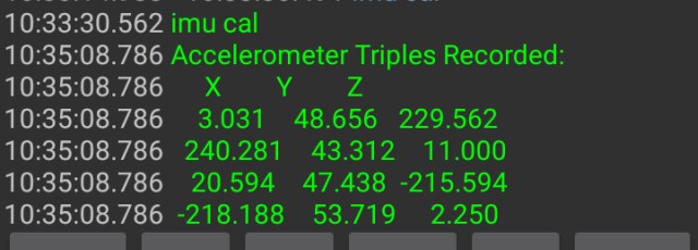
The full set of results can be seen by typing “udp list” and then the key
The values would typically be the following sort of range:imuXScale = 0.00435086
imuYScale = 0.00459159
imuZScale = 0.00448255
imuZDepthCorrection = 0
imuXOffset = 11
imuYOffset = 43.125
imuZOffset = 7.125
imuRange = 2To exit, type “hibernate”.
5.1.4 Check and Set the Tag Time/Date
5.1.4.1 Check Tag Time/Date
To check the tag time and date, once connected using Bluetooth, type “time” and then press the key. The time is a 24hr clock and must be in UTC and needs to be accurate to within a few seconds. See below on how to set the date and time.
5.1.4.2 Set Tag Time/Date
To set the tag time and date, first establish a Bluetooth connection using the Serial Bluetooth App. Once connected, use the time function with the following syntax. The date and time can be set separately, changing one does not change the other.
For the date, type:
“time yyyy-mm-dd”.For the time, type:
“time hh:mm:ss”.Alternatively, both may be changed at the same time by typing:
“time yyyy-mm-dd hh:mm:ss”.Remember to check the date and time are set correctly afterwards by typing “time”.
(NOTE: Commands are case-sensitive). The time is a 24hr clock and must be in UTC and needs to be accurate to within a few seconds.
5.1.5 Deployment Preparation
To prepare the tag for deployment, any previous residual dive information/data can be erased from the tag by running the “deploy emp” command, by typing: “deploy emp”.
The tag will run through an erase sequence and then re-boot. The bluetooth connection on the phone will automatically shut-down. The following indicates what you should see:
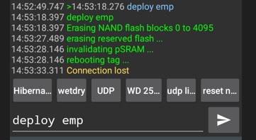
The tag will revert back to standby and is now ready for deployment.
Note: There are instances where certain blocks fail to erase, for example:
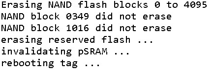
The software scans the available ‘good-blocks’ and only used the good blocks. This is standard practice for such devices (such as SD cards). The green status LED will once again indicate that it is in hibernation mode. The tag is then ready to deploy again.
5.1.6 TDR Data
In addition to transmitting data, the tag logs data to FLASH memory in the form of a TDR record.
Options are available to either download the whole record, or select snapshots within the FLASH memory.
To view the available snapshots, type: “tdr list”.The following is a typical partial screenshot once complete:
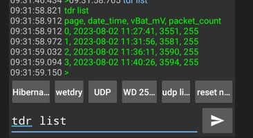
This will show the available pages and the timestamp over which the measurements were made. In this case data is saved in to 4 blocks, or ‘pages’.
To download, use the “tdr list m..n” command, where ‘m’ and ‘n’ specify the lower and upper page ranges.
So, to download the data corresponding to Pages 1 and 2, inclusive, type: “tdr show 1..2”.
Helpful hint: To store the data as a text file, there is an option in Serial Port Mapper to log the screen activity which would include the streamed data from the ‘tdr show…’ command.
This may be activated by pressing the three dots button and selecting the “Data” option, and selecting the “Log” tick-box.
There’s a bit of navigation to work out where the files are saved. It may be stored in the following location:
Main Storage > Android > data > de.kai_morih.serial_bluetooth_terminal > files5.2 Reversion to Standby
5.2.1 Bluetooth Mode
To revert a tag to standby from Bluetooth mode, either follow the process in Section 3.3.1 or Section 3.3.5. It is usually good practice to make sure the FLASH is fully erased though.5.2.2 Mission Mode
To revert a tag to standby from Mission Mode, refer to Section 2.2.5.2 Lake Saimaa
5.2.1 Wet/Dry Load and Threshold Setting
In the past, the Gen1 GSM tag uses a gain resistor of 100KΩ and a threshold of 50.
The corresponding values for the Gen2 GSM tag (3G-Basic) were determined by first making a water sample of the appropriate salinity.
Configure a Gen1 GSM tag with a 100KΩ gain resistor and establish a link with TagConfig using Bluetooth.
Dunk the front end of the tag in de-ionised water and slowly add tap water until the wet/dry threshold reads 50 (This was approximately 100mL tap-water per litre of de-ionised water). This is then approximately the same salinity as Lake Saimaa.
Determine the wet/dry values using a 3G-basic tag in this sample of water for various load resistors. The results are as per the table below:Load Resistance, R (UDP setting) Dry Condition Saimaa Water 698 (15) 3 71 713 (7) 1 73 750 (11) 0 76 767 (3) 2 78 885 (13) 0 90 909 (5) 1 93 971 (9) 1 97 1000 (1) 0 100 2308 (14) 0 221 2481 (6) 0 237 3000 (10) 0 282 3300 (2) 0 306 7674 (12) 1 647 10000 (4) 0 805 33000 (8) 2 1815 Results need to be re-confirmed with tag delivery.
Consensus seems to be to increase the sensitivity (e.g. UDP setting 8 corresponding to 33,000) to give a better use of the dynamic range.
Need to be able to detect wet condition but the tag must sense when gets dry, taking in to account the potential for some microbial growth on the tag, so something like a threshold of 1500.
The tag will never see salt-water so over-sensitivity should not present a problem (in the past high salt/humid air just above the sea has prevented dry condition from being established).
Measurements performed at Lake Saimaa (wetDryLoadSelect 8):
Tag 20351 dry 32 wet 1893
Tag 20356 dry 34 wet 1877
Tag 20369 dry 31 wet 1880
Tag 20370 dry 33 wet 17685.2.2 Tag Check
The tags have been loaded with what I think are correct for Lake Saimaa:
wetDryLoadSelect 8
wetDryThreshold 1500
To verify the tag parameters:- Connect to the tag using Bluetooth
- Dunk the upper part of the tag in the water (underside needs to be out of the water in order for the Bluetooth to work). Front and rear wet/dry lugs both need to be immersed.
- Type the following to initiate a wet/dry reading:
wetDry
The tag will report back the reading (low number for dry, e.g. 35, larger number for wet, e.g. 1800). If you get a number less than 1500 then the threshold is too high and will need to be reduced down to perhaps 200 less than the reading you get in the test. If it’s small then we have a problem. - To set the Wet/Dry Load Resistor, type:
udp wetDryLoadSelect n
where n takes the vale 1-15 in the table earlier ( I would leave this value alone, at 8) - To set the Wet/Dry threshold, type:
udp wetDryThreshold n
where n takes the value of typically 1-3000 - Check values loaded correctly by typing:
udp list wet - Check the udp udpOverride is set correctly by inspecting the udp settings, type
udp list
Check the “udpOverride” value is 0 - Erase all previous deployment data by typing:
deploy emp
Wait for tag to report that the flash has erased and the tag is “rebooting” - The tag is now ready to deploy.
Step 8 is essential as the last thing which is done before final deployment.
5.2 Brackish-Water (Baltic)
The plot below demonstrates the wet/dry response as a function of water salinity for this version of tag. A standard setting of “wetDryLoadSelect 6” was used for the measurements.
In summary, the following default values should be fine for the whole of the Baltic region:
wetDryLoadSelect 6
wetDry Threshold 2121
For completeness the typical response time for a ‘contaminated’ tag (i.e. one which has been soaked in seawater and accumulated a level of bio-film), is as follows: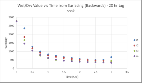
There is no appreciable change following soak.